Views: 0 Author: Site Editor Publish Time: 2026-07-31 Origin: Site
Localized material handling requires robust infrastructure, but the physical construction of a lifting system introduces severe structural liabilities if miscalculated. Facilities need to add lifting capacity—typically 0.5 to 2 tons—without compromising the structural integrity of their concrete slab or exposing the operation to catastrophic failure risks and OSHA violations. A poorly designed base or an out-of-plumb mast leads directly to immediate operational hazards, including trolley drift or complete foundation pull-out under load.
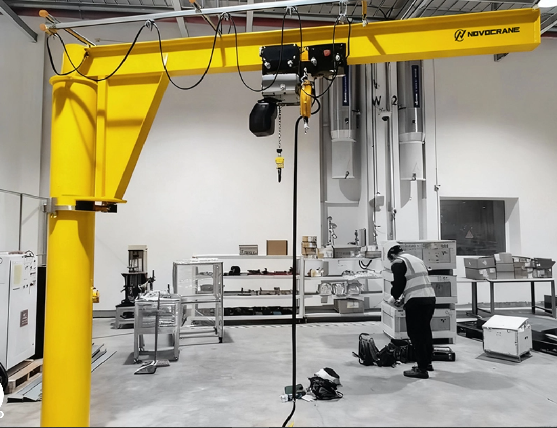
Whether you are fabricating a custom unit or assembling a pre-engineered kit, understanding how to build a floor mounted jib crane requires rigorous evaluation of foundation requirements, structural engineering limits, and precise installation sequencing. You must account for dynamic loading, concrete compressive strength, and strict plumbing tolerances to ensure the equipment operates safely and efficiently within your facility.
Foundation Dictates Feasibility: A standard 6-inch concrete slab is rarely sufficient for high-capacity or long-span cranes; heavy loads often require dedicated, deep-poured footings (e.g., 4x7 feet for a 2-ton, 20-foot radius crane, requiring roughly a full transit-mixer truckload of concrete).
Engineering Liability: Fabricating a crane from scratch carries immense liability; utilizing pre-engineered systems transfers structural liability to the manufacturer while simplifying installation.
Deflection and Tolerances: Proper mast plumbing and boom deflection calculations are critical to prevent "trolley drift" and premature bearing wear.
Compliance is Mandatory: Any built or installed floor mounted jib crane must undergo documented load testing (typically 125% of rated capacity) to comply with OSHA and ASME B30.11 standards before operational use.
Table of Contents
Before cutting steel or breaking concrete, you must define the exact operational parameters of your lifting system. The structural design hinges entirely on precise load calculations, spatial constraints, and expected usage frequency.
Calculating the Maximum Rated Capacity (MRC) involves far more than just weighing the heaviest item you plan to lift. You must account for dynamic loading factors, the dead weight of the hoist, and the trolley weight. When a load is lifted rapidly or stopped suddenly, the dynamic forces exerted on the boom and mast multiply. A system designed to lift 2,000 lbs must structurally support significantly more to maintain a safe working environment and comply with ASME safety standards. Engineers typically apply a 15% to 25% impact allowance for standard electric hoists.
The type of boom you select dictates the crane's footprint, foundation requirements, and operational flexibility on the shop floor.
Feature | Standard Single-Boom Jib | Articulating Jib System |
|---|---|---|
Design | Rigid, straight I-beam or W-flange boom. | Dual-pivot arms with a knuckle joint. |
Best Application | High-capacity, direct, linear transfers. | Navigating around structural columns or tight bays. |
Capacity Range | Up to 5 tons (or more with heavy footings). | Typically limited to 1-2 tons. |
Span | Standard spans up to 30 feet. | Can reach up to 40-foot spans with lighter loads. |
Determine the required boom length based on your floor plan and machine center layout. The span directly impacts the overturning forces applied to the base plate. A longer moment arm exponentially increases the stress on the foundation, requiring thicker concrete, heavier anchor bolts, and a larger base plate footprint. Never specify a longer boom than absolutely necessary, as it unnecessarily inflates the foundation and structural steel requirements.
Evaluate whether your operation requires 360-degree continuous rotation, which is typical of freestanding units, or restricted articulation based on workspace constraints like nearby walls or columns. You must also align the crane's structural fatigue limits and bearing selection with your expected daily operational frequency. Reference the Crane Manufacturers Association of America (CMAA) service classifications (Class A through F) to ensure the bearings and steel can handle the anticipated duty cycle without premature fatigue failure.
The structural integrity of any floor mounted jib crane relies entirely on its foundation. A robust mast and heavy-duty boom are completely useless if the concrete beneath them cracks, shifts, or fails under load.
Never assume your current shop floor can support a crane. Concrete thickness, compressive strength, and underlying soil compaction are primary failure points that must be verified through core testing.
0.5 to 1 Ton Capacity: Standard 150mm (6-inch) reinforced concrete may be suitable for short spans, subject to core testing and localized soil compaction analysis.
2 Ton Capacity: Requires a minimum of 200mm (8-inch) reinforced concrete thickness or a dedicated footing.
Heavier Loads / High Spans: Requires a 300mm+ (12-inch+) reinforced slab or an isolated deep foundation.
You must identify the soil bearing pressure beneath the slab (typically requiring 2,500 to 3,000 PSF minimum) and check for hidden control joints, electrical conduits, plumbing lines, or existing micro-cracks near the proposed mounting site. Mounting too close to a slab edge or expansion joint drastically reduces the concrete's shear strength.
When the existing slab is inadequate, you must excavate and pour a dedicated footing. High-moment loads require significant mass to counteract overturning forces. For example, a 2,000lb self-supporting jib crane with a 20-foot radius typically requires a massive footing measuring 4 feet deep by 7 feet square. This translates to approximately 4.1 cubic yards of concrete.
The new pour must include a properly designed rebar cage utilizing grade 60 steel. The concrete mix must achieve a minimum compressive strength of 3,000 to 4,000 PSI after a 28-day cure. Do not rush the curing process; mounting a crane on green concrete will lead to anchor pull-out.
Anchor bolts secure the mast base plate to the foundation, resisting the massive overturning moment generated by a loaded boom. You must calculate this moment to determine the correct anchor bolt diameter, grade (e.g., ASTM F1554 Grade 36 or Grade 105), and embedment depth.
For new footings, cast-in-place anchor bolts with heavy hex nuts welded to the bottom are standard. For existing slabs, chemical epoxy anchors are vastly superior to mechanical wedge anchors for dynamic loads. Bolt projection length above the concrete is crucial; you must leave enough thread to accommodate leveling nuts, the base plate thickness, heavy washers, the top securing nuts, and a 1-inch to 2-inch gap for structural grouting. Always use rigid steel anchor bolt templates to ensure perfect alignment during the concrete pour, as even a quarter-inch deviation will prevent the base plate from fitting.
If you are designing the system internally, component selection must prioritize rigidity, load transfer, and long-term wear resistance.
Select structural steel pipe that resists bending moments and limits mast deflection under full load. ASTM A53 Grade B or A500 Grade B seamless pipe are common choices. The wall thickness must prevent the mast from bowing. Excessive deflection at the top of the mast translates to significant downward slope on the boom, which directly causes trolley drift and makes manual load positioning nearly impossible for operators.
Size the beam to support the maximum load while minimizing dead weight. Ensure the flange width and thickness are compatible with your selected hoist trolley wheels. An oversized beam adds unnecessary dead weight, increasing the overturning moment on the base and making manual rotation sluggish. Conversely, an undersized beam will deflect beyond the acceptable L/450 ratio (span divided by 450), leading to trolley binding and structural fatigue.
The rotating head must handle both heavy vertical loads (the weight of the boom, hoist, and payload) and severe radial forces (the leverage of the boom pulling away from the mast). Specify heavy-duty thrust bearings for the vertical loads and tapered roller bearings for the radial forces. Design the assembly for easy grease accessibility via standard Zerk fittings, incorporate dust exclusion seals, and ensure the trunnion rollers can be adjusted or replaced without dismantling the entire crane.
The decision to build from raw steel versus buying a pre-engineered kit involves significant risk assessment, engineering overhead, and liability considerations.
Fabricating your own crane requires hiring a licensed structural engineer (PE) to calculate the loads and stamp the custom designs. You assume all welding liabilities. You must utilize AWS D1.1 certified welders and perform non-destructive testing (NDT), such as magnetic particle or ultrasonic testing, on critical structural joints like the base plate gussets and the boom connection points. This approach carries severe commercial insurance implications; if a shop-built crane fails and causes injury, the liability falls entirely on your business.
Some fabrication shops attempt to build a crane to 1-ton structural specifications but down-rate its official capacity tag to 500 lbs to build in a massive safety buffer. While this adds a physical margin of safety against catastrophic failure, down-rating does not exempt a commercial workshop from mandatory OSHA and ASME certification requirements. An inspector will still demand stamped engineering drawings and documented load test results, regardless of the conservative capacity tag.
Pre-engineered kits offer predictable upfront costs, guaranteed ASME/OSHA compliance, and factory-warranted components. They streamline installation by providing manufacturer-approved foundation templates, precise bolt patterns, and detailed assembly manuals. Most importantly, purchasing a kit transfers the structural engineering liability away from your business and onto the manufacturer.
Proper assembly sequencing ensures the crane operates safely, rotates smoothly, and passes initial load testing.
Achieving perfect plumb on the mast is the most critical step in the entire installation. Use heavy-duty leveling nuts on the anchor bolts beneath the base plate to adjust the mast.
Lower the mast onto the anchor bolts, resting on the leveling nuts.
Use a precision machinist level or a laser level on the vertical pipe.
Adjust the leveling nuts until the mast is plumb. The critical tolerance is typically no more than 0.5 inches of variation per 10 feet of vertical mast height. Exceeding this tolerance causes spontaneous trolley drift.
Tighten the top nuts to the specified torque.
Construct a wooden form around the base and pour non-shrink precision epoxy grout beneath the base plate. This ensures 100% load transfer to the concrete foundation and prevents the base plate from flexing on the leveling nuts.
Employ proper rigging and lifting strategies to safely set the head assembly onto the mast. Ensure the thrust bearing is properly seated and heavily lubricated before lowering the head. Verify rotational clearance around the entire 360-degree path and adjust the lower trunnion roller bearing tension according to the manufacturer's specifications to eliminate slop while allowing smooth rotation.
Rig, lift, and secure the boom using bolted or pinned connections. If using bolts, utilize high-strength ASTM A325 or A490 structural hardware. Adhere strictly to torque specifications using calibrated torque wrenches. For A325 bolts, utilize the turn-of-nut method or tension control bolts to ensure proper clamping force. Never reuse structural bolts if they have been fully tensioned once.
Install taglines, C-track festoon systems, or internal slip rings to manage power cables. Slip rings are required if you need continuous 360-degree rotation without tangling cords. Mount the hoist to the trolley, set the upper and lower travel limit switches, and route all power safely to prevent snagging during operation. Ensure the electrical disconnect is easily accessible to the operator.
Anticipating common failures prevents costly downtime, equipment damage, and workplace accidents.
Trolley Drift: Caused by an out-of-plumb mast or a sagging boom. Mitigate this by enforcing strict leveling tolerances during the grouting phase and performing secondary verification under a test load. If drift occurs, you must re-level the mast using the base nuts before the grout is poured.
Foundation Failure: Caused by inadequate concrete depth, poor soil bearing, or mounting too close to a slab edge. Mitigate this by core sampling the slab, conducting soil tests, and adhering strictly to engineering footing guidelines. Never mount a crane over a concrete control joint.
Weld Fatigue: Caused by cyclical loading and poor penetration on DIY builds. Mitigate this by utilizing certified welders following AWS D1.1 structural welding codes, requiring NDT on critical joints, or opting for pre-engineered, factory-welded assemblies.
Bearing Failure: Caused by lack of lubrication or exceeding the duty cycle. Mitigate this by establishing a strict preventative maintenance schedule to grease the thrust and trunnion bearings monthly.
While building a floor mounted jib crane from raw steel is technically possible for a skilled fabrication shop, the structural liabilities, engineering costs, and testing requirements make pre-engineered kits the most viable and safe solution for industrial applications. Base your decision on your existing concrete depth, required load capacity, and internal risk tolerance regarding structural fabrication.
Founded in Suzhou in 2008, Novocrane is a professional manufacturer and service provider specializing in electric hoists, crane systems, and crane components. Combining German design, advanced technology, in-house R&D, and strict load testing, the company provides customized lifting solutions designed for safe and reliable industrial operation.
Consult a licensed structural engineer to evaluate your existing floor slab and determine if a dedicated deep footing is required for your desired capacity.
Request foundation guidelines, anchor bolt templates, and overturning moment calculations from reputable crane manufacturers.
Source a pre-engineered jib crane system that precisely matches your capacity requirements, span needs, and workspace constraints.
Schedule a certified third-party load test using certified test weights to ensure OSHA and ASME compliance before putting the crane into active service.
A: Thickness requirements vary heavily by load capacity and boom span. Generally, 0.5 to 1-ton cranes require a minimum 6-inch reinforced slab. A 2-ton crane typically needs an 8-inch slab or a dedicated footing. Heavy loads or long spans often require 12-inch slabs or deep, isolated foundations.
A: Yes, but it carries immense liability. You must hire a licensed structural engineer to stamp the design, use AWS-certified welders, perform non-destructive weld testing, and pass strict OSHA and ASME load testing certifications before use.
A: For a 2,000lb capacity crane with a 20-foot radius, a typical dedicated footing is 4 feet deep by 7 feet square. This requires approximately 4.1 cubic yards of concrete to safely counteract the massive overturning moment.
A: Trolley drift is caused by an out-of-plumb mast. Prevent it by using heavy leveling nuts to plumb the mast to within 0.5 inches of variation per 10 feet of height, then securing the base plate with non-shrink precision epoxy grout.
A: Yes. Any newly installed, modified, or repaired floor mounted jib crane must undergo documented load testing, typically at 125% of its rated capacity, to comply with OSHA and ASME B30.11 standards before operational use.
A: A freestanding crane uses a single rigid boom for direct linear transfers within a 360-degree radius. An articulating crane uses dual-pivot arms with a knuckle joint to bend around obstacles and reach into tight machinery spaces.
A: Down-rating (e.g., building to 1-ton specs but tagging for 500 lbs) adds a physical safety margin but does not exempt the crane from mandatory engineering stamps, certified welding requirements, and official OSHA load testing protocols.