Views: 0 Author: Site Editor Publish Time: 2026-07-31 Origin: Site
Optimizing localized material handling in facilities with limited floor space and congested production areas remains a persistent industrial challenge. Plant managers constantly face the tension between needing ergonomic, heavy-lifting capabilities at specific workstations and the inability to sacrifice floor footprint for freestanding crane foundations. Navigating this spatial limitation requires a lifting system that integrates directly into the existing facility architecture without disrupting ground-level workflows.
The wall mounted jib crane serves as a high-efficiency, zero-footprint solution to this exact problem. By utilizing the building's own structural columns or reinforced walls, this equipment provides localized lifting power exactly where it is needed. However, its viability hinges entirely on existing building structural integrity and specific workflow constraints. Understanding the mechanical prerequisites, structural demands, and operational limits is essential before integrating this system into your production line.
Zero Floor Footprint: Wall mounted jib cranes eliminate the need for poured concrete foundations, preserving critical floor space for traffic and operations.
Strict Structural Prerequisites: Installation requires rigorous engineering validation of existing building columns or walls to handle specific thrust and pull forces.
Operational Limitations: Unlike freestanding models, stationary wall-mounted variants are typically restricted to a maximum 200-degree rotation and capacities generally capping at 5 tons.
Cost Efficiency: When building structures are adequate, these systems offer significantly lower upfront and installation costs compared to freestanding or overhead bridge cranes.
Table of Contents
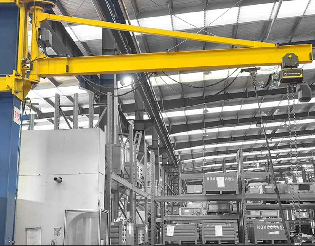
Defining this equipment requires looking through the lens of workstation lifting requirements where floor space is at an absolute premium. A wall mounted jib crane is a specialized material handling device designed to lift, move, and lower materials within a localized semicircular area. Instead of relying on a dedicated vertical mast bolted to a concrete foundation, it anchors directly to a facility's existing structural support system.
Understanding the system requires breaking down its essential components. The boom, often constructed from an I-beam or an enclosed track, serves as the horizontal arm that supports the load. Mounting brackets secure the system to the building; the top bracket handles tension, while the bottom bracket manages compression. The hoist and trolley system travel along the boom to position the load. Finally, the pivot mechanism allows the boom to rotate horizontally, providing the necessary coverage area for the workstation.
Beyond the basic steel structure, the anatomy includes the end stops that prevent the trolley from rolling off the boom, and the trunnion rollers or pivot pins that bear the rotational friction. High-quality pivot mechanisms utilize tapered roller bearings to ensure smooth manual rotation even under maximum load. The structural integrity of these specific connection points dictates the lifespan of the entire lifting system.
The fundamental mechanical difference between this system and a freestanding unit lies in load transfer. When a load is lifted, the weight and the leverage generated by the boom length do not travel down a central mast. Instead, these forces are transferred directly into the existing building structure. The building column acts as the mast. This means the structural integrity of the facility itself dictates the maximum lifting capacity and boom span of the crane.
When an operator moves a load to the furthest tip of the boom, the leverage multiplies the force exerted on the mounting brackets. This creates a massive cantilever effect. The building column must resist not just the downward pull of gravity, but the rotational torque trying to twist the column off its vertical axis. If the column deflects or twists under this load, the boom will slope downward, causing the trolley to roll uncontrollably toward the tip.
Selecting the right equipment requires understanding Crane Manufacturers Association of America (CMAA) Class Service ratings. Jib applications typically fall between Class A (Standby or Infrequent Service) and Class D (Heavy Service). Knowing your cycle rate—how often the hoist lifts a load per hour and the average weight of those loads—is critical. A high-cycle production line requires a crane designed for continuous operation to prevent premature fatigue in the pivot bearings and structural connections.
CMAA Class | Service Level | Typical Application | Load Characteristics |
|---|---|---|---|
Class A | Standby / Infrequent | Maintenance bays, pump rooms | Rarely lifts maximum capacity; slow speeds. |
Class B | Light Service | Light assembly, repair shops | Occasional full loads; 2-5 lifts per hour. |
Class C | Moderate Service | Machine shops, standard manufacturing | 50% capacity average; 5-10 lifts per hour. |
Class D | Heavy Service | Foundries, heavy fabrication | Constant near-capacity loads; 10-20 lifts per hour. |
Facilities have different architectural constraints and lifting requirements. Consequently, manufacturers offer distinct design variations to accommodate specific operational environments. Choosing the wrong configuration can lead to restricted headroom, inadequate reach, or structural incompatibility.
This design utilizes a high-tensile tie-rod connected to the building structure to support the outer end of the boom. The tie-rod runs diagonally from a mounting point above the boom down to the boom's tip. This configuration is best for maximizing hoist travel along the boom and handling heavier capacities with a lighter structural profile. The primary drawback is the requirement for significant overhead clearance above the boom to accommodate the tie-rod angle.
Because the tie-rod handles the tension load, the boom itself can be manufactured from a lighter I-beam. This reduces the dead weight of the crane, making it easier for operators to swing manually. It also reduces the static load on the building column. However, the diagonal rod creates an obstruction. If you have overhead piping, HVAC ducts, or a low ceiling, the tie-rod will interfere with your facility's infrastructure.
In a full cantilever design, the boom is supported entirely by a specialized bracket at the mast or wall connection. There is no tie-rod above the boom. This design is ideal for facilities with low headroom or tight clearance above the workstation. Because the entire load is supported at the base connection, these models are often limited in maximum span and capacity compared to tie-rod models due to higher bending moments exerted on the mounting bracket.
To compensate for the lack of a tie-rod, the boom must be significantly thicker and heavier to resist bending. This increases the dead weight of the system. The mounting brackets are also larger and require a longer vertical mounting footprint on the column to distribute the extreme thrust and pull forces. Cantilever designs are the go-to choice when you need to tuck the crane as close to the ceiling as possible to maximize vertical hook height.
Unlike stationary models, a wall-traveling system is mounted on a longitudinal runway rail system along the building columns. Instead of rotating from a single fixed point, the entire crane travels horizontally down the length of the facility. This provides multi-workstation, rectangular coverage along an entire bay. It serves as an excellent supplement to overhead bridge cranes, though it requires specialized runway engineering and robust column alignment.
These systems are highly complex. They require three separate runways attached to the building columns to handle the vertical load, the outward pull, and the inward thrust. The building columns must be perfectly aligned down the entire length of the bay; any deviation will cause the traveling mechanism to bind. While they offer incredible flexibility by moving the lifting power to wherever it is needed along the wall, the engineering and installation demands are substantial.
The most critical phase of implementing this lifting solution is the structural evaluation. The crane is only as strong as the structure it is attached to. Skipping this step or making assumptions about your building's strength is a direct path to equipment failure and severe safety hazards.
You must evaluate the existing support structure meticulously. Suitable supports typically include heavy-duty H-beams, wide-flange columns, or heavily reinforced concrete columns. Standard drywall, wood framing, or unreinforced masonry is universally incompatible with these systems. Attaching industrial lifting equipment to inadequate supports will result in catastrophic structural failure.
When evaluating steel columns, the thickness of the flange and the web are critical measurements. A column might be capable of supporting the vertical weight of the roof, but completely incapable of resisting the horizontal twisting forces applied by a swinging jib boom. For concrete columns, the internal rebar structure must be known. Drilling into a concrete column without understanding the rebar layout can compromise the column's integrity.
Understanding the physics of the mounting points is essential. When loaded, the top bracket experiences "pull" or tension, attempting to rip away from the wall. Simultaneously, the bottom bracket experiences "thrust" or compression, pushing hard against the support structure. Calculating maximum moment loads requires analyzing the lifting capacity, the boom span, and the distance between the top and bottom bracket centers. The longer the boom, the exponentially higher the thrust and pull forces become.
Consider a 2-ton capacity crane with a 20-foot span. When the load is at the tip, the leverage creates tens of thousands of pounds of force on the brackets. If the distance between the top and bottom brackets is short, those forces are magnified. Increasing the distance between the brackets spreads the load over a larger area of the column, reducing the localized stress. This is why bracket spacing is a non-negotiable engineering specification.
Connecting the crane to the building requires specific hardware configurations based on the structural material. Using the wrong mounting method will lead to loose connections, shifting brackets, and eventual failure.
Bolt-Through Backplates: Best for reinforced concrete walls or solid masonry. This method sandwiches the wall between the crane bracket and a heavy steel backplate, distributing the load across a massive surface area.
Column-Clamping (U-Bolts or Bracket Wraps): Best for structural steel columns. This method wraps around the existing H-beam, avoiding the need to drill holes or weld directly to the building's structural steel, which can weaken the column.
Direct Welding: A permanent integration option. This method requires certified structural welders and is typically used when modifying existing steel columns is permissible and permanent installation is desired.
Industrial lifting equipment must adhere strictly to safety regulations. Compliance with OSHA 1910.179, ASME B30.11, and ASME B30.20 is mandatory. The absolute implementation risk requires a Professional Engineer (PE) to conduct a structural survey. A PE must certify the structural capacity of your building columns before you proceed with procurement or installation.
The PE will calculate the combined stresses on the column, factoring in the dead weight of the crane, the live load of the hoist and material, the dynamic impact factors of lifting, and the existing loads the column already supports (like roof snow loads or wind shear). Only after the PE stamps the approval drawings should any equipment be ordered.
Knowing what the equipment can and cannot do ensures you select a system that aligns with your production workflow. Overestimating the capabilities of a wall-mounted system leads to operational bottlenecks and frustrated operators.
Standard industry capacities for these systems typically range from 1/4 ton up to 5 tons. While heavier custom models exist, they demand massive structural reinforcement. The required capacity directly dictates the necessary structural strength of your building and often limits the maximum feasible boom length.
For loads exceeding 5 tons, the thrust and pull forces usually surpass what standard building columns can safely handle without extensive, highly invasive structural modifications. In those scenarios, a freestanding jib crane or an overhead bridge crane becomes the necessary alternative. The sweet spot for wall-mounted units is in the 1/2-ton to 2-ton range, where they provide excellent ergonomic assistance for machining centers and assembly benches.
Stationary wall-mounted designs have inherent spatial limitations. Standard rotation is physically limited to 180 to 200 degrees because the boom cannot swing through the supporting wall. Maximum boom spans typically range from 10 to 30 feet. As mentioned earlier, increasing the span length exponentially increases the leverage forces exerted on the mounting structure.
Operators must understand this 200-degree limitation. The crane can only serve the semicircular area directly in front of the mounting column. If a process requires moving a part behind the column or in a full 360-degree circle, this equipment is the wrong choice. Proper facility layout planning is required to ensure all pick and drop points fall within this semicircular footprint.
Delivering power to the hoist requires careful planning. Options include manual push/pull systems for lighter loads, flat cable festooning tracks that run along the boom, or taglines. You must also address power supply requirements, determining whether your hoist requires single-phase or three-phase industrial power based on the duty cycle and lifting capacity.
Festooning systems can eat up valuable space on the boom. As the trolley moves toward the wall, the festoon cables bunch up, creating a stack-up dimension that prevents the hoist from reaching all the way to the mounting bracket. If you need the hoist to travel as close to the wall as possible, you must account for this festoon stack-up during the specification phase. Alternatively, enclosed track booms can route the cables internally, minimizing this issue.
The choice of hoist interacts directly with the crane's design to determine the maximum vertical hook path. Wire rope hoists and chain hoists have different dimensional profiles. For tight spaces, ultra-low-headroom hoists maximize vertical lift. Furthermore, environmental adaptations are crucial. Outdoor applications require epoxy coatings, hazardous environments need explosion-proof components, and food-grade facilities demand stainless steel construction.
If the crane is installed in a washdown environment or a chemical processing plant, standard painted steel will corrode rapidly. The pivot bearings must be sealed, and the hoist must carry the appropriate IP (Ingress Protection) rating. Failing to match the equipment's environmental protection to the facility's actual conditions will result in rapid degradation and frequent maintenance failures.
Evaluating the operational advantages of this system requires comparing it against other common material handling solutions. Understanding these trade-offs ensures you deploy the right equipment for the specific task.
The primary conceptual trade-off here is infrastructure versus coverage. A wall-mounted system saves significant resources by avoiding concrete foundation excavation and preserving floor space. However, this comes at the expense of requiring thorough structural engineering assessments and accepting restricted rotation limits (typically 180 degrees compared to the 360-degree rotation of a freestanding unit).
Pouring a new foundation for a freestanding crane involves cutting the existing slab, excavating dirt, tying rebar, pouring concrete, and waiting weeks for it to cure. This disrupts production and creates dust and debris. A wall-mounted unit bypasses this entirely, allowing for a clean, fast installation over a single weekend, provided the building column is already verified as structurally sound.
Comparing these two systems involves analyzing the required coverage area. A jib crane provides localized, circular coverage ideal for a single machine center or assembly station. A workstation bridge crane provides rectangular, multi-workstation coverage across a larger floor area. The choice depends entirely on whether the material handling task is isolated to one spot or requires movement across a broader zone.
If you need to move heavy castings from a pallet, into a CNC machine, and then onto an inspection table all within a 15-foot radius, the wall-mounted jib is perfect. If you need to move that same casting down a 50-foot assembly line passing through multiple workstations, a bridge crane is the necessary solution. The jib crane is a point-of-use tool; the bridge crane is a zone-coverage tool.
Proactive risk management ensures a safe installation and reliable long-term operation. Ignoring these risks leads to damaged infrastructure, injured personnel, and halted production lines.
Mounting heavy equipment to building columns introduces the risk of structural overload. Mitigation requires a mandatory PE structural analysis prior to installation. If columns are borderline acceptable, installing column wrap brackets or reinforcement plates can distribute load stress more effectively. Additionally, implementing routine non-destructive testing (NDT) of critical welds ensures long-term safety.
Over time, the constant cyclic loading of lifting and swinging can cause fatigue in the building column's steel or the mounting bracket welds. Operators must be trained to never exceed the rated capacity and to avoid shock-loading the crane (jerking the load upward suddenly). Annual inspections must focus heavily on the integrity of the mounting hardware and the surrounding building structure.
Introducing a swinging steel beam into a congested workspace creates potential collision hazards. Mitigation involves conducting 3D spatial mapping of the area to ensure the 200-degree swing path does not collide with existing machinery, pallet racking, or overhead utilities. Installing mechanical swing stops on the pivot mechanism physically limits travel and prevents accidental impacts.
If a forklift mast strikes the jib boom, it can severely damage the pivot mechanism or compromise the mounting brackets. The swing path must be clearly marked on the floor, and operators must ensure the boom is parked in a safe, designated position when not in use. Swing stops are critical if the boom's natural rotation path intersects with a pedestrian walkway or a high-traffic forklift aisle.
Manufacturing layouts change over time. When evaluating risk, consider the ease of relocating the equipment. A wall-mounted system clamped to a steel column can be unbolted and relocated with relative ease. This contrasts sharply with the permanent, unrecoverable nature of freestanding concrete foundations, which must be demolished if the facility layout changes.
If you anticipate moving the workstation within the next few years, utilize column-clamping mounting methods rather than direct welding. Clamps allow the entire crane assembly to be taken down and moved to a new column (assuming the new column also passes engineering review) without leaving permanent scars or requiring extensive grinding and repair work on the original structural steel.
A wall mounted jib crane stands as an optimal choice for localized, repetitive lifting tasks in space-constrained facilities, provided the building structure is robust enough to handle the applied forces. It preserves valuable floor space while delivering ergonomic material handling directly to the workstation.
Founded in Suzhou in 2008, Novocrane is a professional manufacturer and service provider specializing in electric hoists, light crane systems, and crane components. Combining German design principles, in-house research and development, advanced technology, and strict quality control, the company provides customized lifting solutions for a wide range of industrial applications.
To move forward with implementing this solution, follow these actionable steps:
Document the precise weight of your heaviest load and the required boom span to reach all necessary pick and drop points.
Locate the original architectural blueprints of your facility to identify the structural composition of your building columns.
Hire a licensed Professional Engineer to conduct a site assessment and certify that your columns can handle the specific thrust and pull forces.
Map out the workstation area to ensure the crane's swing path is clear of overhead obstructions and machinery.
A: Typically ranges from 250 lbs to 5 tons, heavily dependent on the building's structural integrity and mounting configuration.
A: Standard rotation for fixed models is between 180 and 200 degrees, limited by the wall or column it is mounted to.
A: Yes, a Professional Engineer must verify that the existing building column or wall can withstand the specific thrust and pull forces generated by the crane under load.
A: Tie-rod models use a support rod above the boom for higher capacities and smoother hoist travel, while cantilever models support the boom entirely from the mast bracket, ideal for low-headroom areas.
A: While hoists and trolleys are frequently motorized, the rotation of wall-mounted jib cranes is typically manual due to their localized application, though motorized rotation can be custom-engineered for heavy-duty applications.
A: Unlike stationary units, a wall-traveling jib crane is mounted on a longitudinal rail system along the building columns, allowing it to move horizontally along the entire length of a bay to serve multiple workstations.
A: Wall mounted units are generally less expensive upfront and avoid the high costs of excavating and pouring a concrete foundation, provided the existing building structure requires minimal reinforcement.