Views: 0 Author: Site Editor Publish Time: 2026-10-13 Origin: Site
Selecting lifting equipment is a critical engineering decision that dictates the safety, efficiency, and uptime of your overhead crane system. Underspecifying equipment leads to premature motor burnout, brake failure, and the severe risk of dropped loads on the facility floor. Overspecifying wastes capital and places excessive deadweight on your bridge structure, which can trigger unnecessary structural reinforcement costs. You need a systematic evaluation framework to prevent these missteps. This guide aligns hoist capabilities with specific lifting profiles, facility constraints, safety requirements, and industry duty cycle standards. By evaluating operational needs against mechanical realities, you can integrate an electric hoist that delivers reliable performance under demanding industrial conditions. We will break down the exact specifications required to keep your production line moving safely.
Electric hoist selection must begin with an accurate assessment of the duty cycle (CMAA/FEM/ISO classifications) and workstation beat, not just the maximum load capacity.
The choice between electric chain and wire rope hoists depends heavily on capacity requirements, continuous operating times, and lateral pulling risks.
Site-specific constraints—such as available headroom, ambient temperature, and power supply stability—frequently override standard catalog specifications.
Precision requirements dictate the motor control strategy, requiring a choice between single-speed, dual-speed, or Variable Frequency Drive (VFD) configurations.
Integrating modern safety features and ergonomic control interfaces (like properly sized pendants or radio remotes) is essential for operator protection and compliance.
Table of Contents
The fundamental mechanism of the lifting equipment determines its physical footprint, maintenance schedule, and suitability for heavy industrial use. You must choose between a chain-driven system and a wire rope system before looking at any other specifications. This core architecture dictates how the unit handles lateral forces, how much headroom it consumes, and how it responds to high-frequency operations on the factory floor.
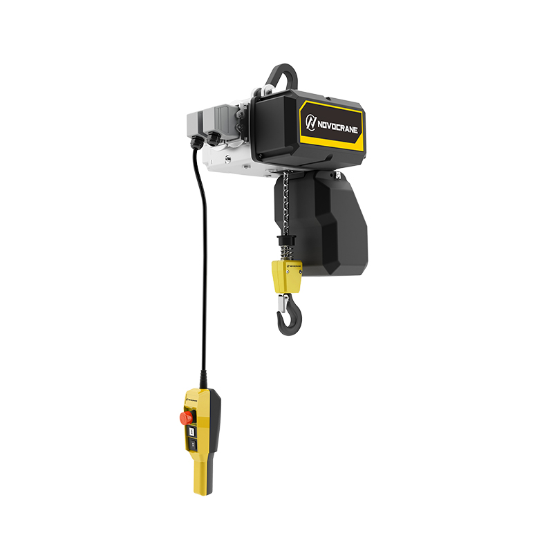
Electric chain hoists use motor-driven sprockets and steel chains to lift loads, typically in the 5–10 ton range or below. Their compact design and minimal lateral hook movement make them suitable for workshops, jib cranes, and precision assembly. However, chain wear, lubrication requirements, and lifting speed limitations may restrict their suitability for intensive operations.
Electric wire rope hoists use steel cables wound around grooved drums to handle heavy loads, often ranging from 10 to 100 tons or more. They offer higher lifting speeds and are well-suited for demanding industrial applications. However, their larger structure requires more installation space, while regular wire rope inspections and proper spooling are essential for safe operation.
Specification Parameter | Electric Chain Hoist | Electric Wire Rope Hoist |
|---|---|---|
Optimal Capacity Range | 0.25 to 10 Tons | 10 to 100+ Tons |
Physical Footprint | Compact, minimal headroom required | Large, requires significant drum housing |
Lifting Speed | Slower, limited by sprocket friction | High-speed capable |
True Vertical Lift | Standard (no lateral hook drift) | Requires double-reeving to prevent drift |
Primary Maintenance | Chain lubrication, sprocket wear gauging | Rope inspection, rope guide replacement |
Duty Cycle Tolerance | Light to Moderate | Heavy to Severe Continuous |
Translating basic operational needs into precise technical specifications ensures the equipment performs reliably under real-world conditions. You cannot rely on rough estimates or guesswork. Every parameter must account for peak operational demands, heavy rigging hardware, and unpredictable operator behavior.
Safe Working Load (SWL) selection must account for the heaviest load, lifting attachments, and rigging equipment. Dynamic forces during lifting can increase equipment stress, making proper capacity selection essential. Operators should avoid shock loading and ensure the total suspended weight remains within the hoist's rated capacity.
Lift height determines the vertical distance a hoist must move a load. Wire rope hoists require suitable drum capacity, while chain hoists need adequate chain storage. Applications requiring precise positioning should consider true vertical lift to minimize lateral hook movement and improve lifting accuracy.
Lifting speed control affects operational efficiency, positioning accuracy, and equipment safety. Different control systems are available for specific lifting requirements.
Control Type | Main Advantage | Suitable Application |
|---|---|---|
Single-Speed | Simple and cost-effective | General material handling |
Dual-Speed | Fast lifting with slow positioning | Machinery installation and assembly |
Variable Frequency Drive (VFD) | Smooth acceleration and precise speed control | Precision lifting and frequent operations |
Hoist control interfaces influence operator safety and working efficiency. Wired pendants provide reliable direct control and should be positioned at a comfortable operating height. Wireless radio remotes allow operators to maintain a safer distance from suspended loads and improve visibility during lifting. The appropriate control system depends on workspace layout and operational requirements.
Matching the equipment to the correct duty cycle and workstation beat is the single most important factor in preventing premature failure. A unit rated for intermittent maintenance use will destroy its motor and gear train within weeks if placed on a high-volume automotive production line.
CMAA, FEM, and ISO classifications help evaluate hoist duty requirements based on lifting frequency, load intensity, and operating time. CMAA Classes A–F describe crane service conditions, while FEM ratings classify hoist mechanisms. Proper duty selection helps prevent motor overheating, gearbox wear, and premature equipment failure.
Frequent lifting operations generate heat in electric hoist motors, increasing the risk of overheating and insulation damage. Heavy-duty motors may use cooling fans, heat-dissipating housings, and thermal protection sensors. Selecting suitable cooling and motor protection ensures reliable performance during repeated lifting cycles.
Headroom determines the available vertical lifting space beneath an overhead crane. Standard trolley configurations are suitable for facilities with sufficient clearance, while low-headroom trolleys position the hoist closer to the beam. Proper trolley selection maximizes lifting height and improves workspace efficiency.
Electric hoists must match the facility's voltage, phase, and frequency requirements. Incorrect power supply or excessive voltage drops can cause reduced lifting performance, motor overheating, and electrical failures. Proper electrical sizing and voltage verification help maintain safe operation.
Operating conditions influence hoist material selection, electrical protection, and maintenance requirements. Outdoor, dusty, humid, or high-temperature environments may require additional protection.
Operating Environment | Recommended Protection |
|---|---|
Dusty or Wet Areas | Suitable IP-rated enclosures |
Hazardous Locations | Appropriately certified explosion-protected equipment |
High Temperatures | Heat-resistant components and suitable lubrication |
Cold Environments | Low-temperature materials and condensation protection |
Electric hoist safety features protect operators, equipment, and suspended loads. Buyers should evaluate overload protection, travel limit switches, braking systems, and compliance with applicable lifting equipment standards.
Overload protection systems prevent lifting beyond the equipment's rated capacity. Mechanical slip clutches or electronic load monitoring systems help reduce excessive loading risks. Upper and lower limit switches restrict hook travel, preventing overtravel and potential damage to the lifting mechanism.
Electric hoist braking systems hold suspended loads securely during operation and power interruptions. Spring-applied electromagnetic brakes automatically engage when power is removed. Critical lifting applications may require additional braking arrangements based on applicable safety standards and risk assessments.
Selecting the correct lifting equipment requires rigorous attention to mechanical and environmental details. To ensure a successful implementation, follow these final steps:
Audit your current lifting operations to determine your exact maximum loads, including all below-the-hook rigging devices and impact factors.
Calculate your true duty cycle by tracking motor starts per hour and average load weights during peak production shifts.
Measure your facility's exact available headroom and verify your three-phase voltage at the runway conductor bar.
Consult with a structural engineer if you are increasing the lifting capacity on an existing bridge beam.
Specify VFD controls and secondary mechanical brakes for any applications involving fragile loads or hazardous materials.
A: Calculate the maximum weight of the heaviest item you will lift, then add the exact weight of all rigging hardware, spreader beams, and lifting devices. Add a 15-20% buffer to this total to account for dynamic shock loading and prevent premature wear on the gear train.
A: It is possible, but it requires verifying that the existing motor is inverter-duty rated. Standard motors may overheat when run at low speeds via a VFD because their internal cooling fans spin too slowly. You will also need to replace the control panel and contactors.
A: Overheating usually stems from exceeding the unit's rated duty cycle, operating in ambient temperatures above the motor's rating, or experiencing significant voltage drops from the power supply, which forces the motor to draw excessive amperage.
A: Operators should perform a visual inspection daily before the first lift, checking for obvious kinks or broken wires. A qualified technician must perform a comprehensive, documented inspection monthly or quarterly, depending on the severity of the duty cycle and environmental conditions.
A: A standard headroom trolley mounts the main lifting body directly below the bridge beam. A low headroom trolley mounts the body parallel to the beam, tucking the machinery up higher. This reclaims vertical space, allowing higher hook lifts in buildings with low ceilings.
A: On standard wire rope units, the cable spools horizontally across the grooved drum as the hook rises. This horizontal movement pulls the hook slightly to one side. To eliminate this, you must specify a double-reeved unit, which uses two ropes spooling toward the center simultaneously.